One of the customer projects that I have done involves creating a 'bed of nails' rig that flashes initial firmware onto a board that uses an ATMel XMega processor. It uses an AVR ISP Mk II device, connected via USB to a Raspberry Pi Model 2, which flashes the initial firmware and controls the process. It also uses a USB Bluetooth adaptor to perform bluetooth communications during the test, and a proprietary command/control to run the various tests on the boards. The Raspberyy Pi Model 2's GPIO pins control the device under test, powering it on and off, sensing various parameters, sensing button presses, and controlling the LCD display. The basic test process takes around 5 minutes, nearly all of which is automated. It is possible for a single technician to run several of these tests simultaneously, when using multiple 'bed of nails' devices.
Since I had been the primary engineer on this project for 2 years (at that time), it was much less of a problem to design this system, since I had already written a number of 'self-test' features for the firmware. It was just a matter of automating them and integrating the process. The biggest problem was the time it took for a single person to perform the testing and flashing, which was SIGNIFICANTLY more than the 5 minutes that the 'bed of nails' device takes, perhaps 4 or 5 times as long, and only one board at a time. This wasn't acceptable for a limited production run, and the process was unnecessarily tedious when done manually.
As a result, an automated test rig was needed. The rig had to be capable of being modified, in case the board design changed, while being able to retain as much from the previous design as possible. Normally such a device could run more than $10,000 to have built. It's nearly always a custom test unit, and there are companies that specialize in building such things. I was able to build two of them for signicantly less than this amount, and building additional bed of nails devices (or modified versions to support a change to the board layout) would be relatively cheap (and could be done by a technician other than myself).
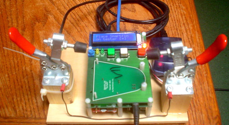
The above photo shows an overall view of the bed of nails device, with the LED display prompting the user to begin the test. There are 3 pushbuttons located directly below the LCD screen, one marked 'Yes', one marked 'No', and the power button. A device known as the ATX Raspi allows the power button to energize the device, and to safely shut down the power, since the Raspberry Pi has no power control circuitry, and is running a version of Linux. There is also a 5V linear regulator on board that is capable of powering up the device under test. A linear regulator was chosen since it's more tolerant of power surges. Otherwise, energizing a faulty unit, even through a PTC fuse, might reboot the Raspberry Pi Model 2.
Additional circuitry on the board allows various GPIO pins on the Raspberry Pi to control and sense various parameters during the test, from voltage levels to pushbutton input to controlling the LCD display. The LCD itself is an inexpensive device that normally requires 7 I/O pins; however, based on a design that I used for the S.F.T. Power Supply, I was able to use a shift register, that also doubled as a level converter, to drive 7 pins with only 3 of the GPIO pins (1 clock, 1 data, 1 'enable'), via a method similar to SPI.
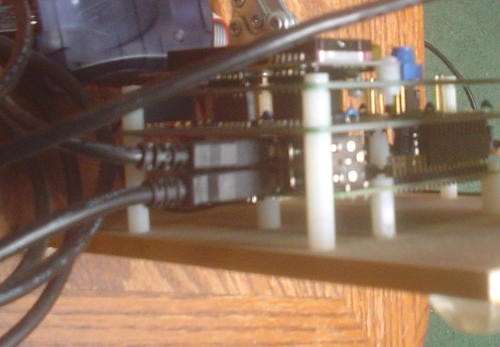
As you can see in the above photo, there are 2 custom boards on top, separated by nylon spacers. The spacing allows the pogo pins to extend through the top board, perfectly aligned (due to the holes drilled into the top board), and also protecting them against being bent laterally. Underneath the middle board is the Raspberry Pi and the ATX Raspi control board. Various components are mounted on both sides of the board for the power supply, including the 5V linear regulator, which has a heat sink underneath (not visible from this angle), and the filter capacitor, since it is too large to fit anywhere else.
The entire assembly is screwed down (via nylon screws and spacers) to a wooden board, and a ground wire connects to the two board clamps. The board under test is aligned onto 2 nylong screws, and the clamps hold it in place while it is being tested. The operator will press a series of buttons, answering questions on the LCD display, regarding the type of board being tested. Each board option has identical test points so that the same unit can be used for all of them. Then the test proceeds, validating the operation of the board, generating test data, and downloading the test data. Once the test is complete, the green LED will light, and the board is de-energized, and the operator can then remove it and prepare another board for testing.