A brief history
An "Operational Amplifier", or "Op Amp", is a type
of electronic circuit that is a 'block element' representing many discrete components, or since the
invention of the integrated circuit, a single device containing the circuit. It consists of inverting
and non-inverting inputs, and can have a single output, or a 'balanced' (inverting and non-inverting)
output. Typically they amplify only the difference in voltage (or current) of the two inputs, with a
significantly high gain (often 10,000 or more), rejecting variations in power supply and common input
signal. They often have split (+/-) power supplies, and normally operate at the 'zero' potential that
lies between them. Many Op Amps will operate 'rail to rail', allowing inputs voltage to meet (or even
exceed) the power supply voltage in either direction, although the output may only approach these
voltages.
Op Amp Basics
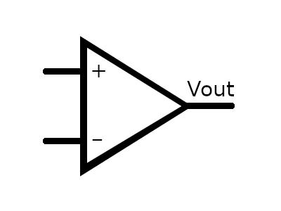
The diagram at the top shows the basic block diagram for an Op Amp. The '+' signifies the non-inverting
input, where an increase in voltage/current in the positive direction results in an increase in the
output voltage in the positive direction. The '-' signifies the inverting input, for which (as you probably
guessed) an increase in voltage/current in the positive direction results in an increase in the NEGATIVE
direction on the output. As mentioned, the gain of the op amp is applied to the difference in these two
input signals. Ideally when both are connected together, the output voltage will be centered between the
positive and negative power supplies. Unfortunately this is rarely the case, so some kind of Negative
Feedback will be needed for the operational amplifier to work properly.
The concept of Negative Feedback can be shown in the diagram below, which shows 3 basic Op Amp circuits.
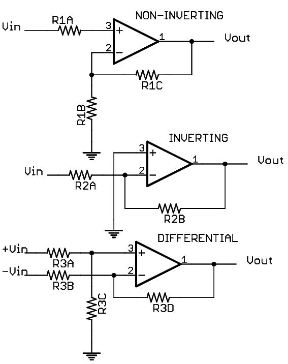 One is an inverting amplifier, one is a non-inverting amplifier, and the third is a differential amplifier,
an amplifier that uses the difference between the inputs as the signal to amplify. In each case, a resistor
ladder sends a fraction of the output voltage back to the inverting input. This fraction determines the gain
of the overall circuit.
One is an inverting amplifier, one is a non-inverting amplifier, and the third is a differential amplifier,
an amplifier that uses the difference between the inputs as the signal to amplify. In each case, a resistor
ladder sends a fraction of the output voltage back to the inverting input. This fraction determines the gain
of the overall circuit.
In the example at the right, the non-inverting amplifier uses R1C as the 'feedback' resistor, and
R1A and R1B should have matching values. R1B is actually an input resistor for the inverting input, which
is connected to ground. The inverting input goes through a resistor with a matching value (R1A), and so
the single-ended input signal is "differential to ground". If a voltage of 1V were applied to
the input, the output voltage would be equal to the gain times the input voltage, where
gain = (R1C + R1B) / R1B
assuming that the Op Amp has sufficient internal gain and a resonable enough zero offset voltage
on its inputs to faithfully reproduce the signal.
So, if R1a and R1B were both 1K resistors, and R1C were a 9K resistor, then applying an input voltage of
1 Volt should result in an output of 10 Volts.
Here is why
- Applying 1 Volt to the input of the circuit theoretically has a potential of 1 Volt on the non-inverting
input (or a corresponding current).
- For the circuit to be 'in balance', you would need approximately the same voltage (or current) on the
inverting input.
- To achieve this balance, a 10 Volt output drops 9 Volts across R1C, and 1V across R1B.
- As long as the voltage on the non-inverting input (or its current) is higher than the voltage on the
inverting input (or its current), the output will increase. As it increases, the voltage (or current)
on the inverting input increases proportionally.
- Similarly, if the non-inverting input is lower than the inverting, the output voltage will decrease
(become less positive and/or more negative) until the circuit is in balance.
This is essentially how negative feedback works, particularly with an Op Amp, to stabilize the circuit and
provide a fixed gain. It also tends to negate the effects of component variability and distortion of the
signal, noise injection, and so forth. In the real world, noise and distortion just happen. Negative
feedback minimizes this.
Similarly, for the inverting amplifier, the gain would be determined by
gain = (R2B + R2A) / R2A
|
©2020 by Stewart~Frazier Tools, Inc. - all rights reserved
Last Update: 10/17/2020
Back to S.F.T. Inc. main page
|